73 In. (1850 mm) Global Materials Bucket - BW15937
 Materials bucket
Materials buckets may be used for loading dirt, gravel, feed, and light materials as well as scraping, digging, and other general-purpose tasks.
NOTE: Materials buckets are not compatible with replaceable cutting edges or digging teeth.
85 In. (2150 mm) Global Heavy Duty Bucket With Grapple Brackets - BW15918
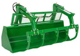 Heavy-duty bucket (shown with grapple)
85 In. (2150 mm) Global High Volume Bucket - BW16006
The high-volume bucket is intended for use with lighter-density high-volume materials. The bucket capacity makes this an effective tool for handling snow, wood shavings, and other loose materials.
85 In. (2150 mm) Global Materials Bucket - BW15936
Materials bucket Materials buckets may be used for loading dirt, gravel, feed, and light materials as well as scraping, digging, and other general-purpose tasks.
NOTE: Materials buckets are not compatible with replaceable cutting edges or digging teeth.
73 In. (1850 mm) Global Heavy Duty Bucket - BW15935
Heavy-duty bucket (shown with grapple)
E-ICV Valve and Parts (3rd Function) - BW15118
E-ICV Valve and Parts (3rd Function) - BW15987
E-ICV Valve and Parts (3rd Function) - BW15988
Mid-Mount E- ICV Valve and Parts (3rd Function) - BW15314
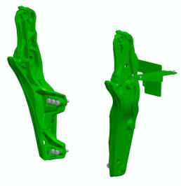
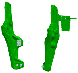
 Hood guard for 5E 4-cylinder and 5M Series Tractors
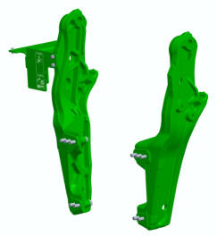
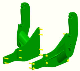
 Hood guard for 6D and 6E Series Tractors
The heavy-duty hood guard is compatible with 5E 4-cylinder, 5M, 6D, and 6E Tractors.
NOTE: See below for details on tractor family, series, and model years.
The basic function of a hood guard is to:
- Help protect the tractor grille and hood from falling debris or stationary objects such as a wagon or mixer
- Allow for lighting at night
The hood guard:
- Can be used without the loader for additional protection to the front of the tractor
- Can be used with or without the tractor front weight bracket but not with the actual front weights while using the loader (this would overload the front axle)
- For the 5M Series Tractors, the bottom bar must be removed for usage with front hitch for storage position of the center link.
It is highly recommended to purchase a front weight bracket when using a loader. The hood guard is designed to be slightly rearward of the front weight bracket. This is so the front weight bracket is the first point of contact against lower stationary objects.
If a front weight bracket is not used, the lower bar can be moved downward to improve the protection of the grille below the lights.
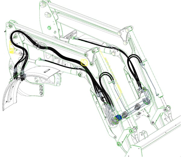
Hoses and Parts (3rd Function) - BW16069
Hoses and Parts (3rd Function) - BW16187
Hoses and Parts (3rd Function) - BW16103
Hoses and Parts (3 Function) - BW15845
Hoses and Parts (2 Function) - BW15844
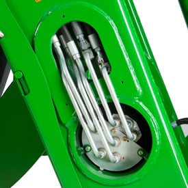
3 Function Mid-Mount Single Point Hydraulic Connection, Loader Half - BWA1546
Kit, 3rd Function Single Point Connection Parts - BW16132
Kit, 3rd Function Quick Coupler Parts - BW16133
Grapple Coupler Oil Lines and Bracket, Quick Couplers - BW16048
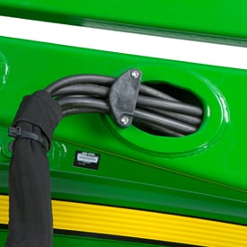
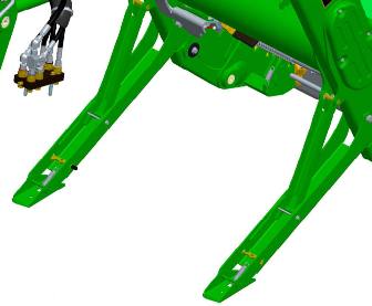
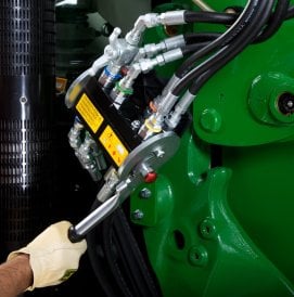
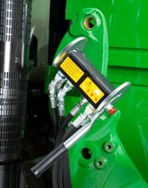
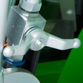
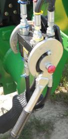
Two function
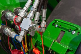 Two function quick coupler
The H240, H260, H310, H340, and H360 Loaders feature two-function quick-couplers in base machine. To disconnect the hydraulic connection between the loader and the tractor, it is necessary to relieve the hydraulic system oil pressure on the tractor.
To watch a video of how to use quick couplers click here.
NOTE: this video is intended to show the functionality of quick couplers only. Location of the connection varies across different loaders.
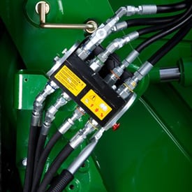
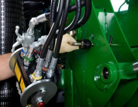
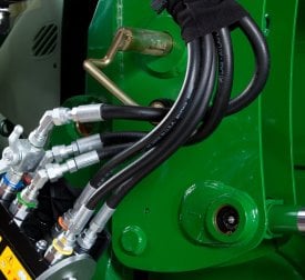
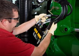
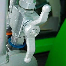
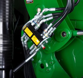
Three function
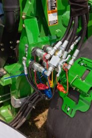 Three function quick coupler
The H240, H260, H310, H340, and H360 Loaders can be equipped with three-function quick-couplers. Hoses will be installed in the boom arm and just the couplers will need to be assembled along with the third-function bracket and oil line. To disconnect the hydraulic connection between the loader and the tractor, it is necessary to relieve the hydraulic system oil pressure on the tractor.
3 Function Single Point Hydraulic Connection - BWA1581
3 Function Single Point Hydraulic Connection - BWA1588
3 Function Quick Couplers - BW16124
3 Function Quick Couplers - BW16051
3 Function Multi-Coupler, Loader Half - BW16401
3 Function Multi-Coupler - BW16402
3 Function Multi-Coupler - BW16075
3 Function Mid-Mount Quick Couplers - BWA1580
Two function
Two function quick coupler The H240, H260, H310, H340, and H360 Loaders feature two-function quick-couplers in base machine. To disconnect the hydraulic connection between the loader and the tractor, it is necessary to relieve the hydraulic system oil pressure on the tractor.
To watch a video of how to use quick couplers click here.
NOTE: this video is intended to show the functionality of quick couplers only. Location of the connection varies across different loaders.
Three function
Three function quick coupler The H240, H260, H310, H340, and H360 Loaders can be equipped with three-function quick-couplers. Hoses will be installed in the boom arm and just the couplers will need to be assembled along with the third-function bracket and oil line. To disconnect the hydraulic connection between the loader and the tractor, it is necessary to relieve the hydraulic system oil pressure on the tractor.
2 Function Single Point Hydraulic Connection - BW16399
2 Function Single Point Hydraulic Connection - BW16400
2 Function Single Point Hydraulic Connection - BW16100
2 Function Single Point Hydraulic Connection - BW16074
3 Function Mid-Mount Quick Couplers - BWA1589
Two function
Two function quick coupler The H240, H260, H310, H340, and H360 Loaders feature two-function quick-couplers in base machine. To disconnect the hydraulic connection between the loader and the tractor, it is necessary to relieve the hydraulic system oil pressure on the tractor.
To watch a video of how to use quick couplers click here.
NOTE: this video is intended to show the functionality of quick couplers only. Location of the connection varies across different loaders.
Three function
Three function quick coupler The H240, H260, H310, H340, and H360 Loaders can be equipped with three-function quick-couplers. Hoses will be installed in the boom arm and just the couplers will need to be assembled along with the third-function bracket and oil line. To disconnect the hydraulic connection between the loader and the tractor, it is necessary to relieve the hydraulic system oil pressure on the tractor.
2 Function Single Point Coupler, Loader Half - BW15914
2 Function Mid-Mount Quick Couplers - BW16123
Two function
Two function quick coupler The H240, H260, H310, H340, and H360 Loaders feature two-function quick-couplers in base machine. To disconnect the hydraulic connection between the loader and the tractor, it is necessary to relieve the hydraulic system oil pressure on the tractor.
To watch a video of how to use quick couplers click here.
NOTE: this video is intended to show the functionality of quick couplers only. Location of the connection varies across different loaders.
Three function
Three function quick coupler The H240, H260, H310, H340, and H360 Loaders can be equipped with three-function quick-couplers. Hoses will be installed in the boom arm and just the couplers will need to be assembled along with the third-function bracket and oil line. To disconnect the hydraulic connection between the loader and the tractor, it is necessary to relieve the hydraulic system oil pressure on the tractor.
2 Function Mid-Mount Quick Couplers - BW16052
Two function
Two function quick coupler The H240, H260, H310, H340, and H360 Loaders feature two-function quick-couplers in base machine. To disconnect the hydraulic connection between the loader and the tractor, it is necessary to relieve the hydraulic system oil pressure on the tractor.
To watch a video of how to use quick couplers click here.
NOTE: this video is intended to show the functionality of quick couplers only. Location of the connection varies across different loaders.
Three function
Three function quick coupler The H240, H260, H310, H340, and H360 Loaders can be equipped with three-function quick-couplers. Hoses will be installed in the boom arm and just the couplers will need to be assembled along with the third-function bracket and oil line. To disconnect the hydraulic connection between the loader and the tractor, it is necessary to relieve the hydraulic system oil pressure on the tractor.
3 Function SLC, M-ICV, Hoses and Parts - BWA1585
3 Function Single Lever Control, M-ICV, Hoses and Parts for Field Installation - BWA1576
3 Function SLC, M-ICV, Hoses and Parts - BWA1607
The loader hoses are connected to the mid-tractor selective control valves (SCVs).
3 Function SLC, M-ICV, Hoses and Parts - BWA1568
The loader hoses are connected to the mid-tractor selective control valves (SCVs).
3 Function SLC, M-ICV, Hoses and Parts - BWA1566
The loader hoses are connected to the mid-tractor selective control valves (SCVs).
3 Function SLC, M-ICV, Hoses and Parts - BWA1587
The loader hoses are connected to the mid-tractor selective control valves (SCVs).
Single Level Control and Valve (3 Function) - BW15774
3 Function Hydraulic Hoses and Parts - BWA1615
3 Function Hydraulic Hoses and Parts - BWA1614
3 Function Hydraulic Hoses and Parts - BWA1591
Hoses and Couplers (2 Function) - BW15637
Hoses and Parts (2 Function) - BW16102
The loader hoses are connected to the mid-tractor selective control valves (SCVs).
Mid-Mounted Independent Control Valve (2 Function) - BW15985
Mid-Mounted Independent Control Valve (3 Function) - BW15986
Single Level Control and Valve (2 Function) - BW15773
Single Lever Control and Mounting Parts (2 or 3 Function) - BW15744
Single Lever Control and Mounting Parts (3 Function with GSS) - BW15785
Single Lever Control and Mounting Parts (3 Function with GSS) - BW15807
Single Lever Control and Mounting Parts (3 Function with GSS) - BW15784
2 Function Hoses and Parts - BW16635
The loader hoses are connected to the mid-tractor selective control valves (SCVs).
3 Function Hydraulic Hoses and Controls - BWA1570
2 Function Hoses and Parts - BW16068
2 Function Hoses and Parts - BW16186
The loader hoses are connected to the mid-tractor selective control valves (SCVs).
2 Function SLC, M-ICV, Hoses and Parts - BWA1510
2 Function SLC, M-ICV, Hoses and Parts - BWA1586
The loader hoses are connected to the mid-tractor selective control valves (SCVs).
2 Function SLC, M-ICV, Hoses and Parts - BWA1565
The loader hoses are connected to the mid-tractor selective control valves (SCVs).
2 Function Single Lever Control, M-ICV, Hoses and Parts for Field Installation - BWA1575
3 Function Hoses and Parts - BW16636
The loader hoses are connected to the mid-tractor selective control valves (SCVs).
3 Function Hydraulic Hoses and Controls - BWA1577
3 Function Hydraulic Hoses and Controls - BWA1578
3 Function Hydraulic Hoses and Controls - BWA1569
3 Function Hydraulic Hoses and Parts - BWA1590
Stationary fenders - BW15906
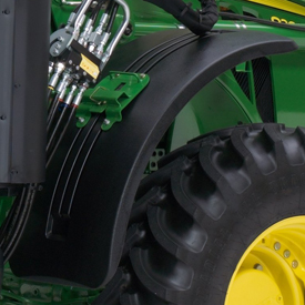 Stationary fender (H480 shown)
Loader stationary fenders are highly recommended for those operating in conditions where the front axle will be in full oscillation and turn frequently or where tight turns are made while maneuvering through gates or obstacles that will catch tractor axle-mounted fenders.
The loader stationary fenders still provide coverage for debris from the tire, but they do not protrude to become damaged in operation. The fenders can be removed to enable better access for servicing as well.
Stationary fenders - BW16094
Stationary fender (H480 shown) Loader stationary fenders are highly recommended for those operating in conditions where the front axle will be in full oscillation and turn frequently or where tight turns are made while maneuvering through gates or obstacles that will catch tractor axle-mounted fenders.
The loader stationary fenders still provide coverage for debris from the tire, but they do not protrude to become damaged in operation. The fenders can be removed to enable better access for servicing as well.
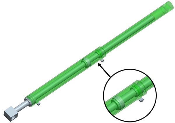
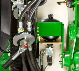
Loader suspension system with operator station on and off switch - BW16070
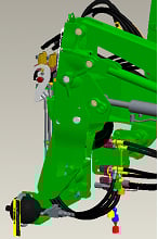
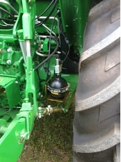
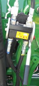
 Nitrogen-charged accumulator and electric valve
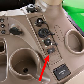 Operator on/off switch
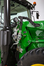
 LSS on H180
 LSS on 5E and 5M
An enhancement to the loader is the suspension system. A great level of loader productivity is achieved with the LSS.
- An accumulator charged with nitrogen and connected to the head-end lift cylinder hose through a T-fitting provides shock absorption
- The cylinders move in and out to allow the boom to float
Performance
- Bales can be transported more efficiently from one end of the field to the other over frozen, hard-packed, or rutted terrain.
NOTE: Check bale handling capability of tractor before use.
- Pallets can be moved easily without sustaining cargo damage
- Pallets of seed or fertilizer can be carried across a yard without a bag spilling and creating a costly mess
- Properly ballasted tractor with LSS has increased stability, creating a smoother ride for the operator
Cost of Ownership
Reasons for turning LSS off include:
- Digging applications - With LSS on, the cylinders retract slightly, losing lifting power
- Holding a grade when blading - With LSS on, it is difficult to hold a constant grade
- Precise pallet and bale handling - With LSS on, the load moves up and down slightly while being positioned
- Parking a loader - With LSS on, when down pressure is applied, the lift cylinders retract slightly, making it more difficult to park
The switch is conveniently located in the operator station to avoid having to exit the operator station to manually move the handle on the LSS.
LSS can also be ordered with a manual shutoff. Depending on the tractor/loader model, the accumulator is located in different places. On the H180 the accumulator is mounted outside the bottom of the mounting frame. On the 5 Series tractors, the accumulator is mounted near the inside of the rear right wheel. On 6 series tractors and larger, it is mounted in between the hydraulic connection and the mounting frame.
Loader suspension system with operator station on and off switch - BW15797
Nitrogen-charged accumulator and electric valve
Operator on/off switch
LSS on H180
LSS on 5E and 5M
An enhancement to the loader is the suspension system. A great level of loader productivity is achieved with the LSS.
- An accumulator charged with nitrogen and connected to the head-end lift cylinder hose through a T-fitting provides shock absorption
- The cylinders move in and out to allow the boom to float
Performance
- Bales can be transported more efficiently from one end of the field to the other over frozen, hard-packed, or rutted terrain.
NOTE: Check bale-handling capability of tractor before use.
- Pallets can be moved easily without sustaining cargo damage
- Pallets of seed or fertilizer can be carried across a yard without a bag spilling and creating a costly mess
- A properly-ballasted tractor with LSS has increased stability, creating a smoother ride for the operator
Cost of ownership
Reasons for turning LSS off include:
- Digging applications - with LSS on, the cylinders retract slightly, losing lifting power
- Holding a grade when blading - with LSS on, it is difficult to hold a constant grade
- Precise pallet and bale handling - with LSS on, the load moves up and down slightly while being positioned
- Parking a loader - with LSS on, when down pressure is applied, the lift cylinders retract slightly, making it more difficult to park
The switch is conveniently located in the operator station to avoid having to exit the tractor seat to manually move the handle on the LSS.
LSS can also be ordered with a manual shutoff. Depending on the tractor/loader model, the accumulator is located in different places. On the 440R, the accumulator is mounted outside the bottom of the mounting frame. On the 5 Series Tractors, the accumulator is mounted near the inside of the rear right wheel. On 6 Series tractors and larger, it is mounted in between the hydraulic connection and the mounting frame.
Loader suspension system with operator station on and off switch - BW15866
Nitrogen-charged accumulator and electric valve
Operator on/off switch
LSS on H180
LSS on 5E and 5M
An enhancement to the loader is the suspension system. A great level of loader productivity is achieved with the LSS.
- An accumulator charged with nitrogen and connected to the head-end lift cylinder hose through a T-fitting provides shock absorption
- The cylinders move in and out to allow the boom to float
Performance
- Bales can be transported more efficiently from one end of the field to the other over frozen, hard-packed, or rutted terrain.
NOTE: Check bale-handling capability of tractor before use.
- Pallets can be moved easily without sustaining cargo damage
- Pallets of seed or fertilizer can be carried across a yard without a bag spilling and creating a costly mess
- A properly-ballasted tractor with LSS has increased stability, creating a smoother ride for the operator
Cost of ownership
Reasons for turning LSS off include:
- Digging applications - with LSS on, the cylinders retract slightly, losing lifting power
- Holding a grade when blading - with LSS on, it is difficult to hold a constant grade
- Precise pallet and bale handling - with LSS on, the load moves up and down slightly while being positioned
- Parking a loader - with LSS on, when down pressure is applied, the lift cylinders retract slightly, making it more difficult to park
The switch is conveniently located in the operator station to avoid having to exit the tractor seat to manually move the handle on the LSS.
LSS can also be ordered with a manual shutoff. Depending on the tractor/loader model, the accumulator is located in different places. On the 440R, the accumulator is mounted outside the bottom of the mounting frame. On the 5 Series Tractors, the accumulator is mounted near the inside of the rear right wheel. On 6 Series tractors and larger, it is mounted in between the hydraulic connection and the mounting frame.
Loader suspension system with manual on and off lever - BW16125
Nitrogen-charged accumulator and electric valve
Operator on/off switch
LSS on H180
LSS on 5E and 5M
An enhancement to the loader is the suspension system. A great level of loader productivity is achieved with the LSS.
- An accumulator charged with nitrogen and connected to the head-end lift cylinder hose through a T-fitting provides shock absorption
- The cylinders move in and out to allow the boom to float
Performance
- Bales can be transported more efficiently from one end of the field to the other over frozen, hard-packed, or rutted terrain.
NOTE: Check bale-handling capability of tractor before use.
- Pallets can be moved easily without sustaining cargo damage
- Pallets of seed or fertilizer can be carried across a yard without a bag spilling and creating a costly mess
- A properly-ballasted tractor with LSS has increased stability, creating a smoother ride for the operator
Cost of ownership
Reasons for turning LSS off include:
- Digging applications - with LSS on, the cylinders retract slightly, losing lifting power
- Holding a grade when blading - with LSS on, it is difficult to hold a constant grade
- Precise pallet and bale handling - with LSS on, the load moves up and down slightly while being positioned
- Parking a loader - with LSS on, when down pressure is applied, the lift cylinders retract slightly, making it more difficult to park
The switch is conveniently located in the operator station to avoid having to exit the tractor seat to manually move the handle on the LSS.
LSS can also be ordered with a manual shutoff. Depending on the tractor/loader model, the accumulator is located in different places. On the 440R, the accumulator is mounted outside the bottom of the mounting frame. On the 5 Series Tractors, the accumulator is mounted near the inside of the rear right wheel. On 6 Series tractors and larger, it is mounted in between the hydraulic connection and the mounting frame.
Loader suspension system with manual on and off lever - BW15816
Nitrogen-charged accumulator and electric valve
Operator on/off switch
LSS on H180
LSS on 5E and 5M
An enhancement to the loader is the suspension system. A great level of loader productivity is achieved with the LSS.
- An accumulator charged with nitrogen and connected to the head-end lift cylinder hose through a T-fitting provides shock absorption
- The cylinders move in and out to allow the boom to float
Performance
- Bales can be transported more efficiently from one end of the field to the other over frozen, hard-packed, or rutted terrain.
NOTE: Check bale-handling capability of tractor before use.
- Pallets can be moved easily without sustaining cargo damage
- Pallets of seed or fertilizer can be carried across a yard without a bag spilling and creating a costly mess
- A properly-ballasted tractor with LSS has increased stability, creating a smoother ride for the operator
Cost of ownership
Reasons for turning LSS off include:
- Digging applications - with LSS on, the cylinders retract slightly, losing lifting power
- Holding a grade when blading - with LSS on, it is difficult to hold a constant grade
- Precise pallet and bale handling - with LSS on, the load moves up and down slightly while being positioned
- Parking a loader - with LSS on, when down pressure is applied, the lift cylinders retract slightly, making it more difficult to park
The switch is conveniently located in the operator station to avoid having to exit the tractor seat to manually move the handle on the LSS.
LSS can also be ordered with a manual shutoff. Depending on the tractor/loader model, the accumulator is located in different places. On the 440R, the accumulator is mounted outside the bottom of the mounting frame. On the 5 Series Tractors, the accumulator is mounted near the inside of the rear right wheel. On 6 Series tractors and larger, it is mounted in between the hydraulic connection and the mounting frame.
Loader suspension system with manual on and off lever - BW15865
Nitrogen-charged accumulator and electric valve
Operator on/off switch
LSS on H180
LSS on 5E and 5M
An enhancement to the loader is the suspension system. A great level of loader productivity is achieved with the LSS.
- An accumulator charged with nitrogen and connected to the head-end lift cylinder hose through a T-fitting provides shock absorption
- The cylinders move in and out to allow the boom to float
Performance
- Bales can be transported more efficiently from one end of the field to the other over frozen, hard-packed, or rutted terrain.
NOTE: Check bale-handling capability of tractor before use.
- Pallets can be moved easily without sustaining cargo damage
- Pallets of seed or fertilizer can be carried across a yard without a bag spilling and creating a costly mess
- A properly-ballasted tractor with LSS has increased stability, creating a smoother ride for the operator
Cost of ownership
Reasons for turning LSS off include:
- Digging applications - with LSS on, the cylinders retract slightly, losing lifting power
- Holding a grade when blading - with LSS on, it is difficult to hold a constant grade
- Precise pallet and bale handling - with LSS on, the load moves up and down slightly while being positioned
- Parking a loader - with LSS on, when down pressure is applied, the lift cylinders retract slightly, making it more difficult to park
The switch is conveniently located in the operator station to avoid having to exit the tractor seat to manually move the handle on the LSS.
LSS can also be ordered with a manual shutoff. Depending on the tractor/loader model, the accumulator is located in different places. On the 440R, the accumulator is mounted outside the bottom of the mounting frame. On the 5 Series Tractors, the accumulator is mounted near the inside of the rear right wheel. On 6 Series tractors and larger, it is mounted in between the hydraulic connection and the mounting frame.
Digging teeth can be added to the heavy-duty bucket for easier digging in hard ground or for breaking loose hard-packed materials such as manure or silage. Digging teeth are not compatible with replaceable cutting edges.
Power Beyond Spacer - BW15989
Tool Box Bracket - BW15971
Power Beyond Spacer - BW15379
Tool Box Bracket - BW16126
Hoses and Parts (3 Function) - BWA1564
The loader hoses are connected to the mid-tractor selective control valves (SCVs).
3 Function Hoses and Parts - BWA1584
The loader hoses are connected to the mid-tractor selective control valves (SCVs).
2 Function SLC, M-ICV, Hoses and Parts - BWA1567
The loader hoses are connected to the mid-tractor selective control valves (SCVs).
3-Function Quick Couplers - BW16958
3 Function Single Point Hydraulic Connection (tractor and loader half) - BW16960
2-Function Single Point Hydraulic Connection - BW16961
2-Function Mid-Mount Quick Couplers - BW16959
Two function
Two function quick coupler
The H240, H260, H310, H340, and H360 Loaders feature two-function quick-couplers in base machine. To disconnect the hydraulic connection between the loader and the tractor, it is necessary to relieve the hydraulic system oil pressure on the tractor.
Three function
Three function quick coupler
The H240, H260, H310, H340, and H360 Loaders can be equipped with three-function quick-couplers. Hoses will be installed in the boom arm and just the couplers will need to be assembled along with the third-function bracket and oil line. To disconnect the hydraulic connection between the loader and the tractor, it is necessary to relieve the hydraulic system oil pressure on the tractor.
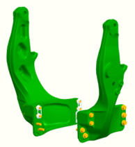
Hood guard for 5E 4-cylinder and 5M Series Tractors
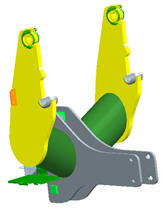
Hood guard for 6D and 6E Series Tractors
The heavy-duty hood guard is compatible with 5E 4-cylinder, 5M, 6D, and 6E Tractors.
NOTE: See below for details on tractor family, series, and model years.
The basic function of a hood guard is to:
- Help protect the tractor grille and hood from falling debris or stationary objects such as a wagon or mixer
- Allow for lighting at night
The hood guard:
- Can be used without the loader for additional protection to the front of the tractor
- Can be used with or without the tractor front weight bracket but not with the actual front weights while using the loader (this would overload the front axle)
- For the 5M Series Tractors, the bottom bar must be removed for usage with front hitch for storage position of the center link.
It is highly recommended to purchase a front weight bracket when using a loader. The hood guard is designed to be slightly rearward of the front weight bracket. This is so the front weight bracket is the first point of contact against lower stationary objects.
If a front weight bracket is not used, the lower bar can be moved downward to improve the protection of the grille below the lights.