| Location (image) |
Component |
Description/notes |
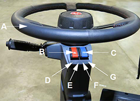
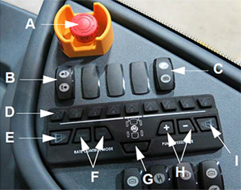
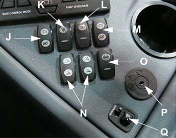
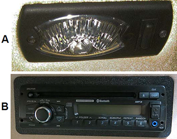
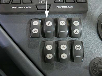
| A |
Emergency stop (e-stop) switch |
The e-stop switch provides a quick method for stopping the engine in an emergency situation. |
| B |
Foam marker switch (if equipped) |
The foam marker switch controls foam application on both sides of the machine. |
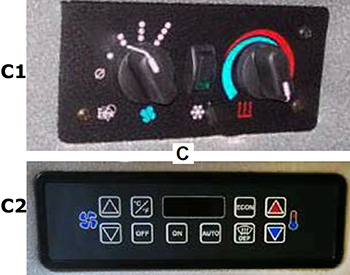
| C |
Rinse switch |
The rinse switch is used to rinse the solution tank and spray booms. |
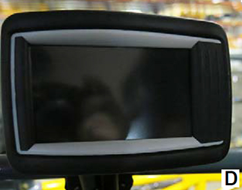
| D |
Boom solution valve switches |
The boom solution valve switches each control a valve located on the boom or transom. The valves control the flow of the solution through the boom. |
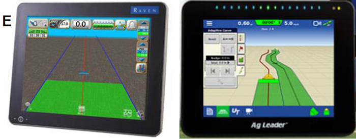
| E |
Fence row switch (left-hand side) |
The fence row switches are used in the selection of either the right or left fence row spray nozzle. |
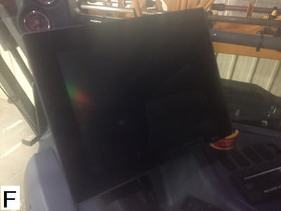
| F |
Rate control switches |
The rate control switches control the rate in which solution is applied through the spray booms by either the rate controller (enable) or operator-controlled spray rate (manual). |
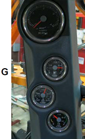
| G |
Rear nozzle switch |
The rear nozzle switch controls the two rear nozzles (located behind the rear tires). |
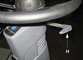
| H |
Pump speed and rate switches |
The pump speed/rate switches allow the operator to increase or decrease flow rate through the spray system. |
| I |
Fence row switch (right-hand side) |
--- |
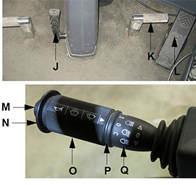
| J |
Main tank valve switch (left-hand side) |
The main tank valve switch controls the solution tank valve. This switch must be in the on (open) position for spray application. |
| K |
Solution pump switch |
The solution pump switch is used to turn the solution pump on or off. |
| L |
Agitation valve switch |
The agitation valve switch controls the rate of flow through the agitation system. |
| M |
Main tank valve switch (right-hand side |
--- |
| N |
Boom extension switches (left/right outer fold) |
The boom extension switches are used to extend or retract the outer boom extensions. |
| O |
Traction valve switch |
--- |
| P |
Ignition switch |
--- |
| Q |
Power mirror switch (if equipped) |
The power mirror switch allows vertical or horizontal adjustment of the electric side-view mirrors by pressing the switch in the desired position. |
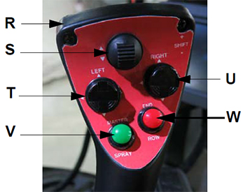
| R |
Hydrostatic drive control handle |
The hydrostatic drive control handle controls the direction of the machine and the speed in which it travels. It is also used to control the spray booms, master spray, end row management, and shift up/down speeds. |
| S |
Transom switch (up/down) |
The transom switch is used to raise and lower the main lift. |
| T |
Right-hand boom switch |
The left- and right-hand boom switches are used to raise, lower, extend, and retract the spray booms. |
| U |
Left-hand boom switch |
The left- and right-hand boom switches are used to raise, lower, extend, and retract the spray booms. |
| V |
Master spray switch |
The master spray switch activates the boom solution valves. |
| W |
End row management switch |
The end-row management switch is a programmable switch that enables various functions (i.e. all-wheel steer, auto steer, master spray, and NORAC® enable) when the switch is depressed. End-row management settings are programmed through the machine display. |
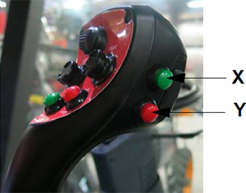
| X |
Shift up switch |
The shift up/down switches are used for speed range selection. |
| Y |
Shift down switch |
The shift up/down switches are used for speed range selection. |
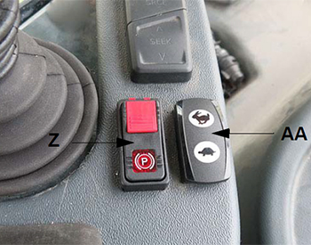
| Z |
Parking brake switch |
The parking brake switch is used to engage and disengage the parking brake, as well as extend and retract the ladder. |
| AA |
Throttle switch |
The throttle switch is used to control engine speed (rpm). |
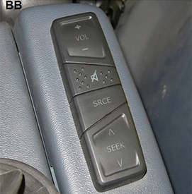
| BB |
Remote stereo controls |
The remote stereo controls are conveniently located to control the stereo (volume, mute, source, and seek). |
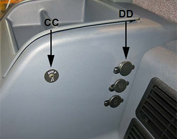
| CC |
12-V power ports |
Four power ports are provided for the connection of additional items (such as radios and computer equipment). |
| DD |
Two auxiliary audio input connections |
The auxiliary audio input allows connection of a personal iPod® device or MP3 player. |