As the largest manufacturer of agricultural and construction equipment in the world, John Deere is committed to providing innovative solutions that help customers be more productive, profitable and successful.
With a wide range of products designed to meet your specific needs, from tractors and combines to site-specific vehicles, you'll find everything you need for success at Everglades Equipment Group with John Deere.
Founded in 1837 when Charles Deere invented his first steel plow, they've been making history ever since by building on what works—products that last longer; dealerships with knowledgeable employees; parts available locally or delivered next day; financing options for all budgets.
Browse our John Deere equipment, text us, call us or go right to the page you know you need.
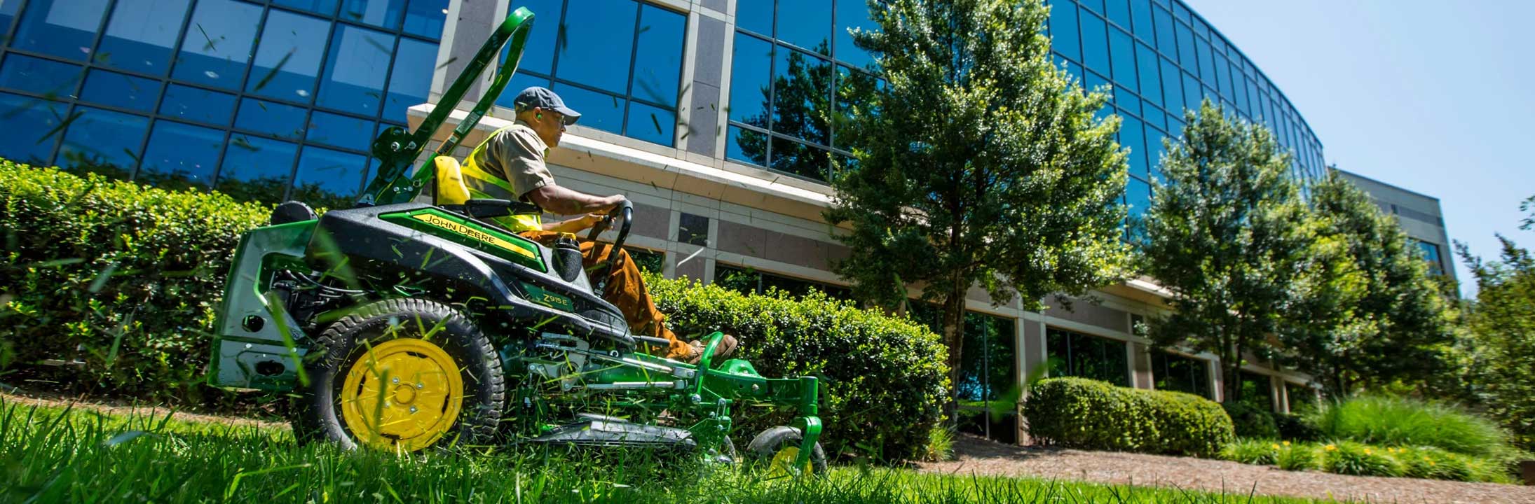
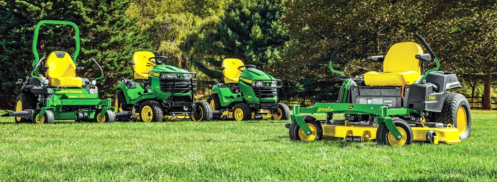
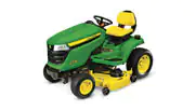
When it comes to getting your yard looking its best, there’s no substitute for quality John Deere equipment – we make sure every product we offer meets our high standards of performance and reliability. That means fewer breakdowns and repairs which saves you money on maintenance costs over the life of your machine as well as making it easier than ever before to find parts when they do wear out from heavy-duty use! With John Deere, all this adds up to one thing – peace of mind knowing that whatever job needs doing around the house will be done right!
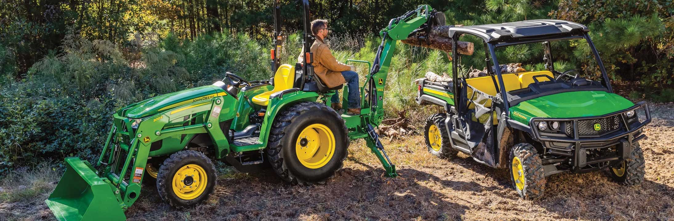
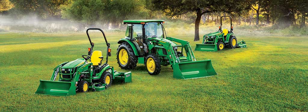
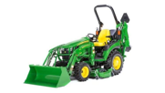
If you’re looking for a compact utility tractor that can handle any job, look no further than the John Deere 1-4 Series Compact Utility Tractors. The 21.5 - 65.9 horsepower engines will have you working at top speed with ease and efficiency while still being able to take on tough jobs like plowing snow (okay, unlikely in Florida) or tilling fields in all types of weather conditions. You won't find another machine that matches this level of performance anywhere else!
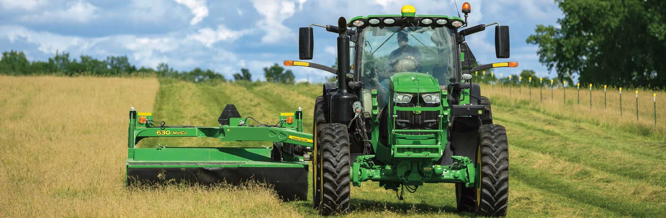
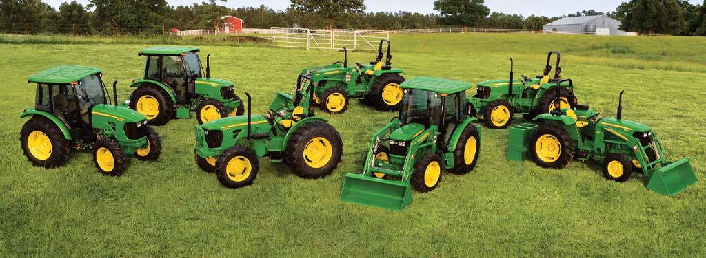
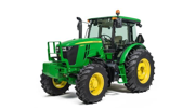
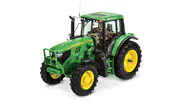
The John Deere 5 and 6 Series Tractors are built for the hardworking people who need a tractor that can handle it all. From working livestock to hay producers to municipalities, these chore tractors bring the horsepower and versatility so you can haul, mow, bale and more. John Deere utility tractors are the perfect choice for any job. Whether you’re looking to work livestock, clear snow or hay, we have the right machine for your needs. With our 5 and 6 Series Tractors, you can expect horsepower and versatility so that you can haul, mow, bale and more. We offer 50-250 horsepower machines to suit your needs.
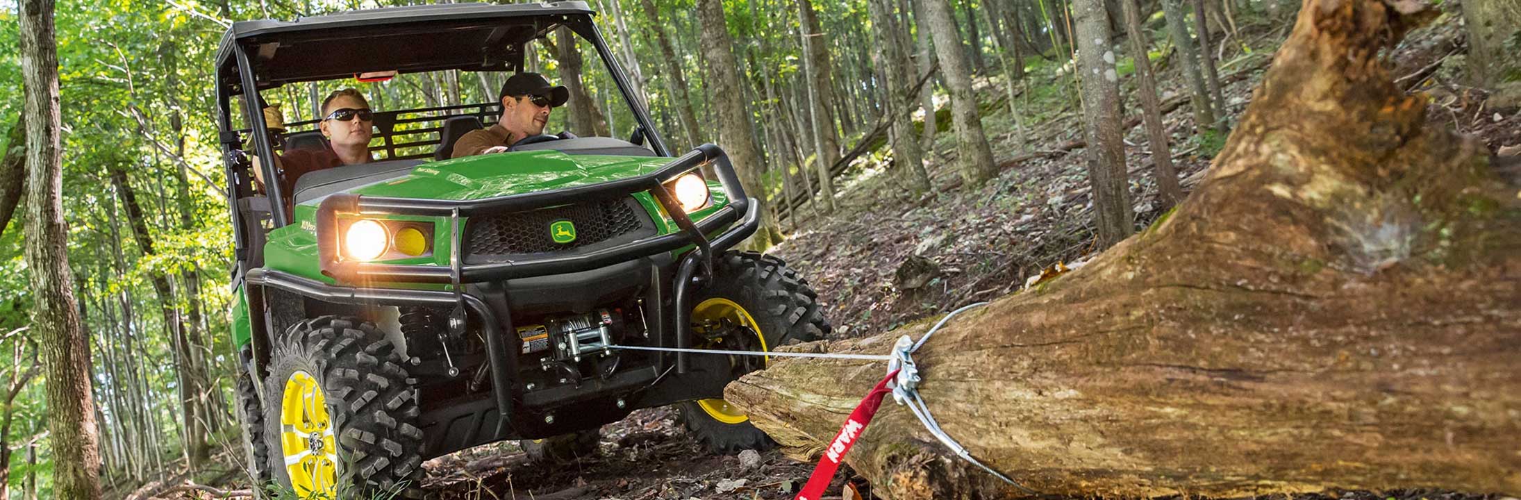
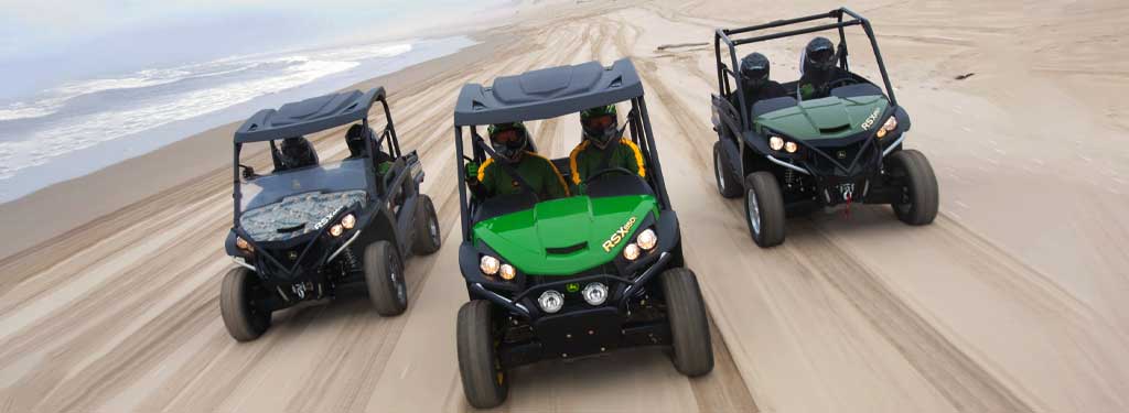
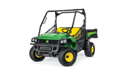
The Gator Utility Vehicle is built tough with an engine that hustles, even when it’s carrying heavy loads. It has a suspension system backed by decades of reliability. And it comes in many sizes – for work or play. Explore more to find the perfect balance of power, speed, and durability in your next side-by-side utility vehicle. John Deere has over 50 years of experience building rugged machines that last long past their warranty date because they know how important utility vehicles are to your business. Explore our lineup today!
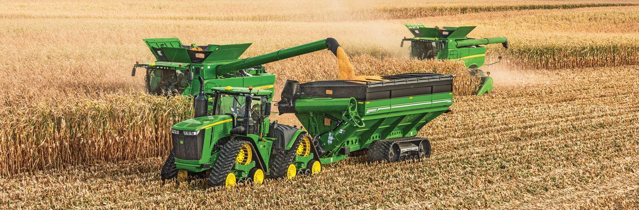
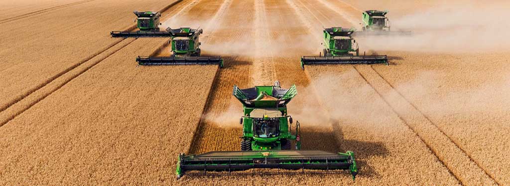
John Deere is the world's largest manufacturer of agricultural equipment and has been since 1837. We offer a wide range of products to suit any farm or ranch operation, from tractors to tillage equipment. Our goal is to help you farm smarter with our innovative solutions that are designed to work better on your land. With over 58 years of experience in agriculture, Everglades Equipment Group knows what it takes to make your operation successful.
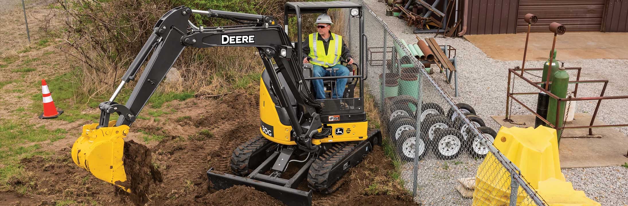
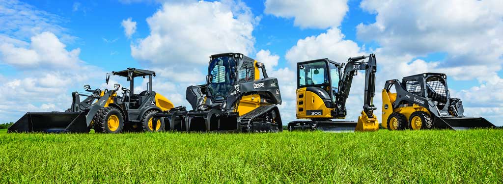
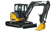
We know how important it is to get your work done efficiently and quickly. That's why we offer a wide range of compact construction equipment so you can find the one best suited to your needs. John Deere's machines are designed with safety in mind so you can focus on what matters most - getting the job done right! From skid steer loaders to mini excavators, you can find the right machine for any size project. John Deere machines are built with quality in mind so they will last through years of hard work.
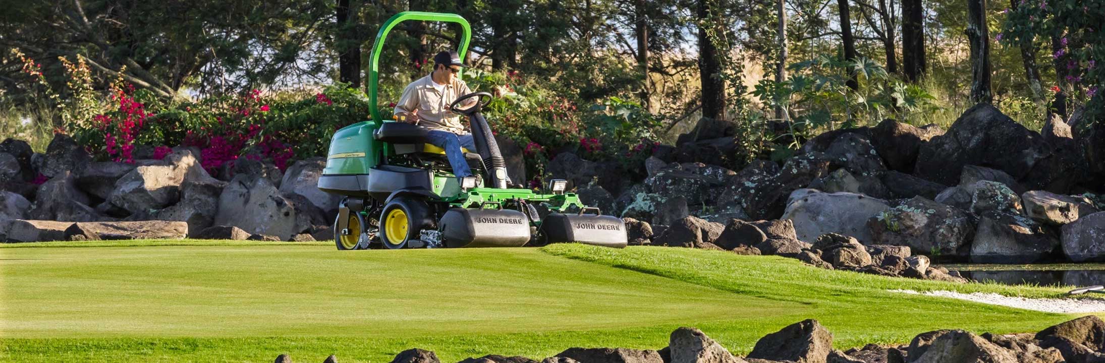
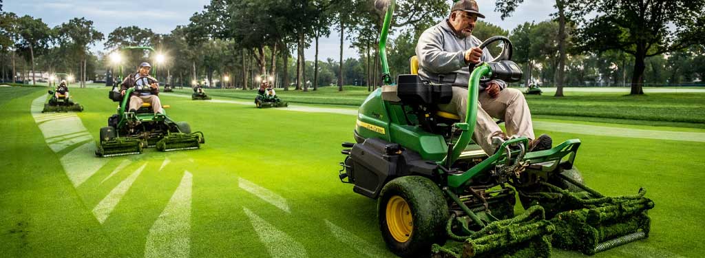
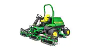
We know that golf courses are a huge investment and can be difficult to maintain. That’s why John Deere has developed precision cutting technology. You won’t find another company like John Deere in this industry. From aeration to bunker rakes, we offer solutions for every field so your golf course is always looking its best!